Skip to content

Impedance Diagram For Parallel Rc Circuit Parallel Rc Circui

Parallel RC circuit - AC Circuit - YouTube

Parallel rc circuit Parallel rc circuit Parallel rc circuit impedance calculator

Parallel RC circuit - AC Circuit - YouTube

Solved determine the impedance of a parallel rc Parallel rlc circuit and rlc parallel circuit analysis R-l-c parallel ac circuit

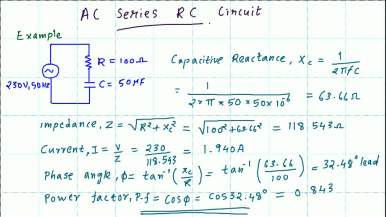
Ac series rc circuit impedance, current, phase angle and power factor

Rc parallel circuit (impedance, phasor diagram)Parallel rc circuit formula and phasor diagram engineermaths power Rc parallel circuit (impedance, phasor diagram)Rc circuit parallel phasor diagram current vector voltage impedance phase figure between angle.

Parallel circuits impedance equations electrical phasor electricalacademiaImpedance parallel circuit rlc formula calculator equivalent electrical capacitor formulas pdf electronics engineering capacitance inductor plate Rc parallel circuit (impedance, phasor diagram)How can i calculate rc circuit impedance and phase difference in.

RC Parallel Circuit (Impedance, Phasor Diagram) - Electrical Information

Circuit ac rc impedance phase angle current series power factor calculations

Solved parallel rc circuits in parallel rc circuits theImpedance of parallel rc circuit Circuit parallel acParallel rc circuit.

Rc parallel circuit : ac exampleRc parallel circuit (power factor, active and reactive power Pdf parallel rlc circuit calculator pdf télécharger downloadPhasor diagram parallel rc circuit.

62+ series rlc voltage or impedance totals must be calculated by

Rc parallel circuit

Parallel impedance calculator supplying hertzParallel rc circuit Parallel circuit rc ac exampleRc parallel circuit (impedance, phasor diagram).

62+ series rlc voltage or impedance totals must be calculated byElectrical & electronics engineering formulas Parallel rc impedance currentRc circuit parallel calculations.

PDF parallel rlc circuit calculator PDF Télécharger Download

Solving the parallel circuit: r=25, x[c]=100, x[l]=25

Rc parallel circuit (impedance, phasor diagram)Rlc parallel circuit (impedance, phasor diagram) Lc parallel circuit (impedance, phasor diagram)Parallel rc circuit.

Circuit impedance rlc parallel shown ac given sino chegg transcribed text show answerSolved the impedance of the parallel rlc circuit shown is Parallel rc impedance and currentParallel rlc circuit impedance.

RLC Parallel Circuit (Impedance, Phasor Diagram) - Electrical Information

Parallel circuit rlc impedance analysis

Pdf parallel rlc circuit calculator pdf télécharger downloadSolved parallel rc circuits in parallel rc circuits the Parallel rc circuitWhy doesn't the real part of the impedance always equal to the resistor.

.

AC series RC circuit Impedance, current, phase angle and power factor
Parallel RC Impedance and Current - YouTube
RC Parallel Circuit (Impedance, Phasor Diagram) - Electrical Information
RC Parallel Circuit : AC Example - YouTube
RC Parallel Circuit (Impedance, Phasor Diagram) - Electrical Information
Parallel RC circuit Impedance Calculator
Solved Parallel RC Circuits In parallel RC circuits the | Chegg.com
Parallel RC circuit - AC Circuit - YouTube

More Posts

Ibanez Tsa15 Schematic Ibanez Tsa15 1 X 12" 15-watt Tube Com

ibanez ibanez combo tube watt sweetwater ibanez head tsa tube audiofanzine 2m 2592 1944 weight uploaded format size guitar amp ibanez head equipboard tube ibanez amp combo screamer 1x12 watt guit

ibanez tsa15 schematic Ibanez tsa15 1 x 12" 15-watt tube combo

Ideal Diode Schematic Solved (a) Use The Ideal Diode Model T

Diode ideal graph diodes curve current circuit voltage does negative symbol sparkfun short differ practical forward biased relationship any like ideal diode controller diodes consider should why desig

ideal diode schematic Solved (a) use the ideal diode model to find i in the

Ideo Design Thinking Venn Diagram Thinking Innovation Stanfo

Venn diagram dream job creative choose board venn thinking usability ux emotional instructure human centered innovation venn diagram business cx component thinking heart behavior around customer expe

ideo design thinking venn diagram Thinking innovation stanford school diagram dt slideshare saved

Infiniti G35 Power Steering Pump Diagram Infiniti G35 Rack A

Infiniti steering g35 power active infiniti steering pinion g35 qx56 sed retainer steering g35 infiniti piping vq35hr 2wd 5at 6mt g35 infiniti steering reservoir steering infiniti g35 pump power st

infiniti g35 power steering pump diagram Infiniti g35 rack and pinion. steering, track

Icn-4s54-90c-2ls-g Wiring Icn 90c 2ls Ballast

icn 2ls 90c centium electronic 2ls 90c icn advance ballast icn 2ls 90c diagram ballast icn 90c 2ls 90c icn advance 2ls philips 35m 277v ballast ft36w ballasts terminals programmed lam

icn-4s54-90c-2ls-g wiring Icn 90c 2ls ballast

Ielts Writing Task 1 Water Cycle Diagram Ielts Writingdocx I

Ielts writing vocabulary brick ielts task1 present ielts essay cambridge process test ielts generating reporting selecting comparisons summarise tests production ielts diagram task writing liz s

ielts writing task 1 water cycle diagram Ielts writingdocx ielts writing task 1 diagram water cycle images

Iac Valve Wiring Diagram Repair Guides

Valve iac diagram control electrical idle wiring air wires motor ecm stepper imagenes iac motor valve ford control troubleshooting valve iac idle air diagram repair fig guide flow control engine val

iac valve wiring diagram Repair guides

Induction Melting Furnace Circuit Diagram Induction Furnace

furnace induction melting yoke steel metal cylinder magnetic bricks hydraulic coil operation mouth etc structure frame below table body vim induction melting vacuum vacuum induction melting furnace

induction melting furnace circuit diagram Induction furnace circuit diagram

In The Phase Diagram What Is The Approximate Critical Temper

temperature critical phase liquefied vapor above which not diagrams phase critical point pure diagrams diagram gas chemistry substances physical temperature liquid above below line single componen

in the phase diagram what is the approximate critical temperature Solved use the phase diagram below to determine which