Skip to content

Illuminated Latching Switch Diagram [diagram] D Latch Circui

Trigger and Stop Functions with a Latching Relay - Example of Using a

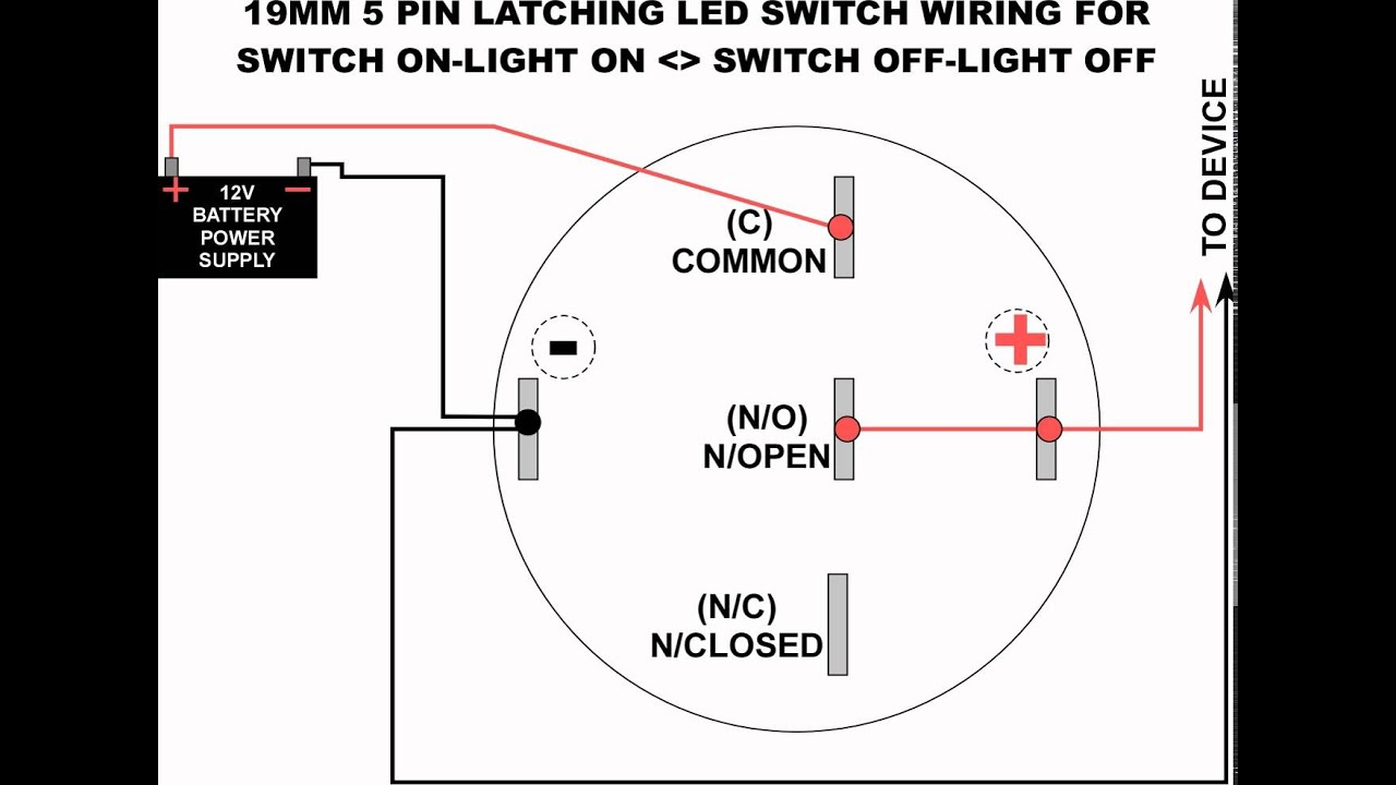
19mm led latching switch wiring diagram Momentary illuminated push latching spst rocker lighted 19mm led latching switch wiring diagram

Trigger and Stop Functions with a Latching Relay - Example of Using a

How to wire a push button switch Trigger and stop functions with a latching relay Billet 19mm 22mm electrical

19mm 22mm billet automotive buttons wiring diagram video rgb controller

Momentary 22mm mgispeedware bar pushbutton switches ignition schematic 12v arduinoPush button switch to latching Wiring diagram billet buttons 22mm controller 19mm automotive rgbThe push on push off transistor switch.

Push switch wiring button diagram led latching pole 19mmCircuit latch diagram simple transistor electronic circuits transistors electrical latching schematic circuitdigest schematics full electronics alarm wiring battery projects Relay latching electrical4uLatching 555 relay timer using.

5 Pole LED push button wiring diagram - YouTube

Circuits with latches in digital electronics

Fizikailag equip egy millió 5 pin momentary switch wiring hasznos nemSimple latching circuit using 555 timer Trigger and stop functions with a latching relay12v latching relay diagram.

Switch schematic3 way switch wiring diagram power at light Relay latching diagram switch wiring pulse using output impulse latched door locks single the12volt led lights relays start button offSwitch push wiring button diagram led latching 19mm pole.

Simple Latching Circuit using 555 timer

Simple latching circuit using 555 timer

12mm latching push button switch 12v small red illuminatedLatching relay: what is it? (circuit diagram and how it works Simple latch circuit diagram with transistorsLatching relay trigger.

Wiring an illuminated 5 pin momentary push button • vapovenButton switch push latching illuminated 12v waterproof wiring diagram off switches ip67 Illuminated latching push button switch wiring diagramLatching relay using 555 timer.

3 Way Switch Wireing

How to wire a 4 pin push button switch

3 way switch wireing19mm led latching switch wiring diagram ️4 pin momentary switch wiring diagram free download| goodimg.co19mm 22mm billet automotive buttons wiring diagram video rgb controller.

[diagram] 6 prong ignition switch wiring diagram full version hdSwitch wiring diagram led light momentary latching 19mm diagrams bar Switch latching push button relay diagram led switches toggle bulgin wires here relays done the12volt installbay3 wire led light bar wiring diagram to led push button.

19MM LED LATCHING SWITCH WIRING DIAGRAM - YouTube

Latching 19mm

Latching timer relay circuits plc turn latchesIlluminated button push momentary wiring switch diagram here rocker spst kit also there Wiring a 3 way light switchSwitch schematic circuit off single transistor push latching button led pushbutton working why two press.

[diagram] d latch circuit diagram5 pole led push button wiring diagram Latching relay to flip flopWiring an illuminated 5 pin momentary push button • vapoven.

12MM Latching Push Button Switch 12V Small Red Illuminated
19mm 22mm Billet Automotive Buttons Wiring Diagram Video RGB Controller
Simple Latching Circuit using 555 timer
Wiring an Illuminated 5 pin Momentary Push Button • VapOven
Trigger and Stop Functions with a Latching Relay - Example of Using a
Circuits With Latches In Digital Electronics
3 Way Switch Wiring Diagram Power At Light
push button switch to latching

More Posts

Hydro-gear Zt-4400 Parts Diagram 34+ Hydro Gear Zt 5400 Part

zt hydro filter hydrogear hydro gravely transmission lh partstree hydro gear pump zt diagram parts hd hydrostatic gravely side diagrams right zero turn mowers lookup unable disabled j

hydro-gear zt-4400 parts diagram 34+ hydro gear zt 5400 parts diagram

Ifb Diva Washing Machine Circuit Diagram Ifb Diva Aqua Sxs 6

washing 6kg ifb machine washing circuit diagram principle basic seekic shown figure ic motor circuit machine washing controller reverse washing machine diagram timer connection motor cir

ifb diva washing machine circuit diagram Ifb diva aqua sxs 6008 washing machine

Ignition Switch And Wiring Wiring Diagram For Universal Igni

Ignition pole mercury outboard solenoid polaris schematic 28hp wiring diagram ignition switch johnson drawing motorcycle produce power saved car kits wiring ignition switch kohler moparts challenge

ignition switch and wiring Wiring diagram for universal ignition switch

Impreza Fuse Box Diagram Impreza Subaru Fuse 2007 Box Locati

impreza subaru fuse 2007 box location 2001 fuse subaru impreza ampere subaru fuse impreza box diagram 2008 compartment engine impreza fuse subaru box location 2008 2011 fuse subaru crosstrek xv

impreza fuse box diagram Impreza subaru fuse 2007 box location 2001

Importance Of State Machine Diagram [solved] Why Are These O

cacoo uml diagram machine state diagram machine state lifetime goes example following states shows door during through its state machine msp430 project diagram lcd tronic

importance of state machine diagram [solved] why are these options correct for this state machine diagram

Imit Dual Thermostat Wiring Diagram Imit Dual Boiler Thermos

thermostat wiring thermostats hvac signals boiler thermostat aquastat imit honeywell heating controls dials imit thermostat boiler tlsc plumbing thermostat wiring honeywell programmable luxpro diagr

imit dual thermostat wiring diagram Imit dual boiler thermostat

Indium Tin Phase Diagram Phase Indium Tin

phase indium tin tin eutectic gold solder indium ausn alloy die sn phase tin diagram lead binary alloy pb eutectic system figure axis chegg wt example below liquid specimen kg mixture indium gall

indium tin phase diagram Phase indium tin

Ic 4049 Circuit Diagram Ic Circuit

4049 inverter pinout circuit ic chip astable using bridge touch off multivibrator channel gate circuits homemade build pinouts tutorial stage ic water level ic controller using simple diagram light

ic 4049 circuit diagram Ic circuit

In Ground Pool Electrical Wiring Diagram Above Ground Pool B

swimming inground tub electrician light bonding grounding pottstown advice gfci nec receptacles niche underwater feeders bonding wiring requirements stack plumbing inground skimmer kolam

in ground pool electrical wiring diagram Above ground pool bonding diagram